What is a Three-Light Outlet Tester?
A three-light outlet tester is a simple device designed to be plugged into an electrical receptacle and by illuminating various combinations of the three lights, it will indicate how the receptacle is wired.
How Does a Three-Light Outlet Tester Work?
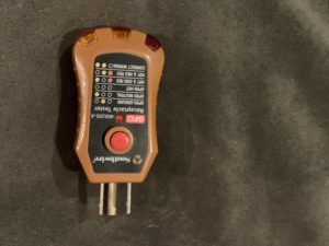
On the three-light receptacle tester shown above, the three lights indicate the following:
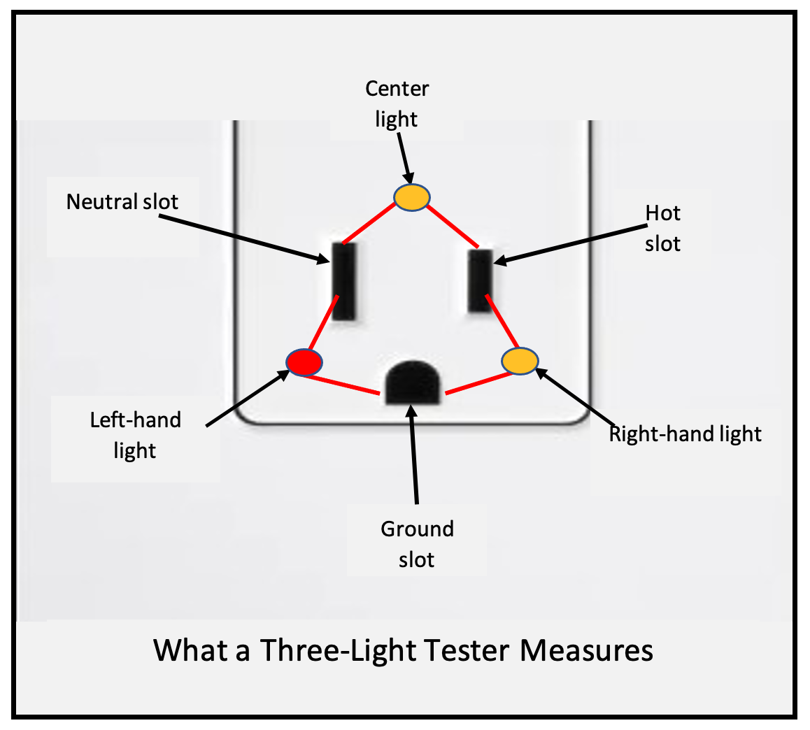
Left-hand light (red) – Lights up if there is a voltage difference between the neutral slot and the ground slot.
Middle light (amber) – Lights up if there is a voltage difference between the neutral slot and the hot slot.
Right-hand light (amber) – Lights up if there is a voltage difference between the hot slot and the ground slot.
(NOTE: Many three-light testers use this same light configuration, but not all do. Therefore, the lights may be arranged differently, but the principle is the same for most, if not all, three-light testers.)
See the illustration below for a visual explanation of what each light means.
It has no way of determining which of the two slots is hot, and which is at zero volts.
This is a limitation of the three-light testers, and this limitation allows it to give an incorrect indication at times.
Properly Wired Receptacle
Let’s look at a quick example.
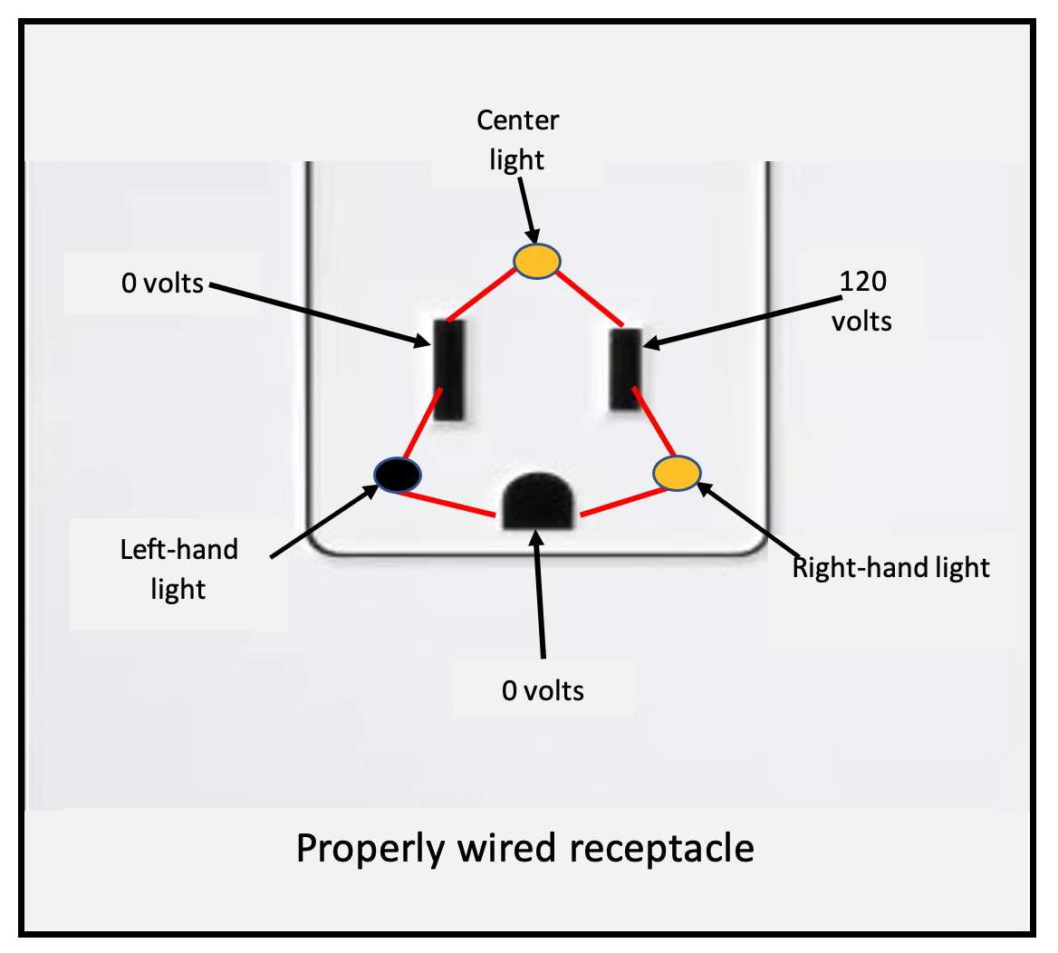
In a properly wired receptacle, you have voltage between the hot and neutral slots, and between the hot and ground slots, but there is no voltage between the neutral and the ground slots.
Bootleg Ground with Reversed Polarity
But wait. There is another way to get this same indication – and it is with a very different wiring configuration.
Granted, you will rarely see this wiring setup, but there is one possible scenario where it could exist.
(The scenario that can give this indication is a reverse polarity in combination with a bootleg ground, shown in this video- Bootleg Ground with Reverse Polarity)
Suppose you have a receptacle with 120 volts on the neutral slot and on the ground slot, and the hot slot is actually connected to ground.
With this configuration, the tester will again read voltage between the hot and neutral, and between the hot and ground. (See the diagram below.)
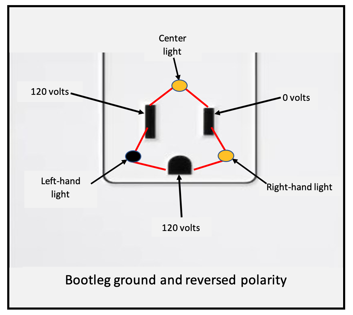
As a result of these voltages, the center light and the right-hand light will illuminate, indicating a correctly wired receptacle; however, as we know, this receptacle is wired about as incorrectly as possible.
Reversed Polarity
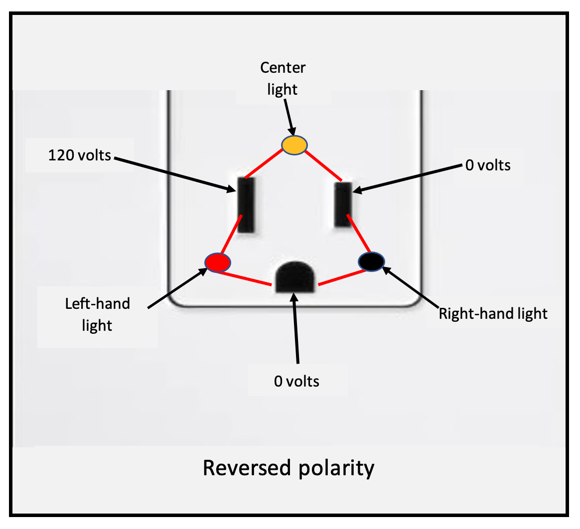
Now, let’s look at an example of a receptacle wired with reversed polarity.
With reversed polarity, the hot and neutral connections have been reversed, so what should be the hot slot is now the neutral, and what should be the neutral slot is now hot.
The tester will obviously detect the 120 volts between the hot and neutral slot, but it will not know that it is wired with reversed polarity. It will just be measuring the voltage between the hot and the neutral slots.
So how does a three-light tester detect reversed polarity??
The only way the tester can differentiate between a correctly wired receptacle and a receptacle wired with reversed polarity is by comparing the voltage on the narrow and wide slots to the voltage on the ground hole.
If the tester measures no voltage between the narrow (hot) slot and ground slot, but instead measures 120 volts between the wide slot (normally neutral) and ground slot, then the left-hand light indicating this voltage difference will illuminate.
With the center and left-hand lights illuminated, the tester is indicating the hot/neutral reverse. See diagram below.
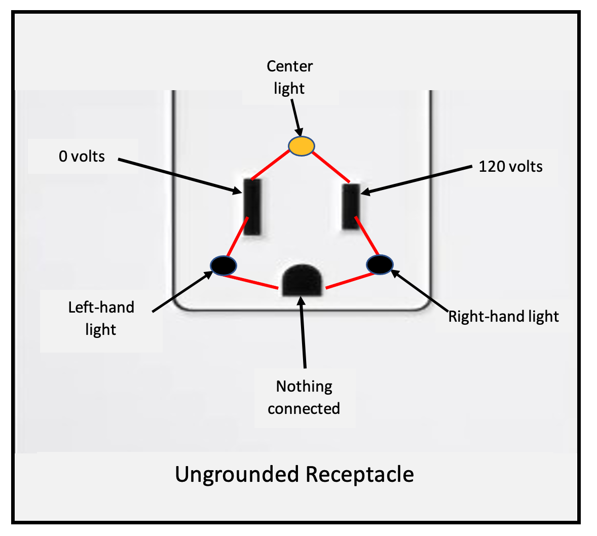
Let’s look at very simple example of a receptacle with an open ground. (See illustrations below)
Open Ground
The hot wire is connected to the narrow (hot) slot, and the neutral wire is connected to the wide slot. Since the receptacle is not grounded, nothing is connected to the ground hole/slot.
When the tester is plugged in, only the center light will come on indicating voltage between the hot and neutral slots.
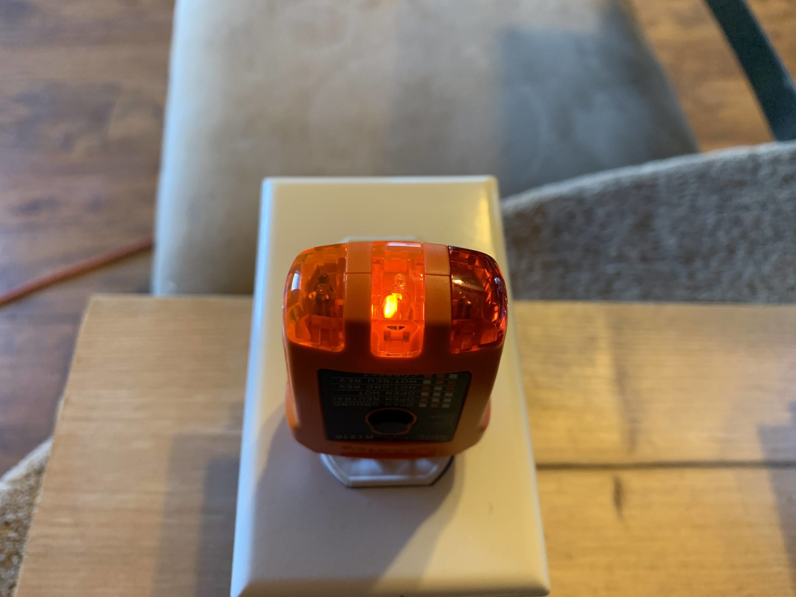
Indication on tester
The hot wire is connected to the neutral slot, and the neutral wire is connected to the hot slot (the opposite of above). Again, nothing is connected to the grounding slot.
When the tester is plugged into this outlet, the center light on the tester will light – again indicating voltage between the hot and neutral slots, but not knowing which slot is hot.
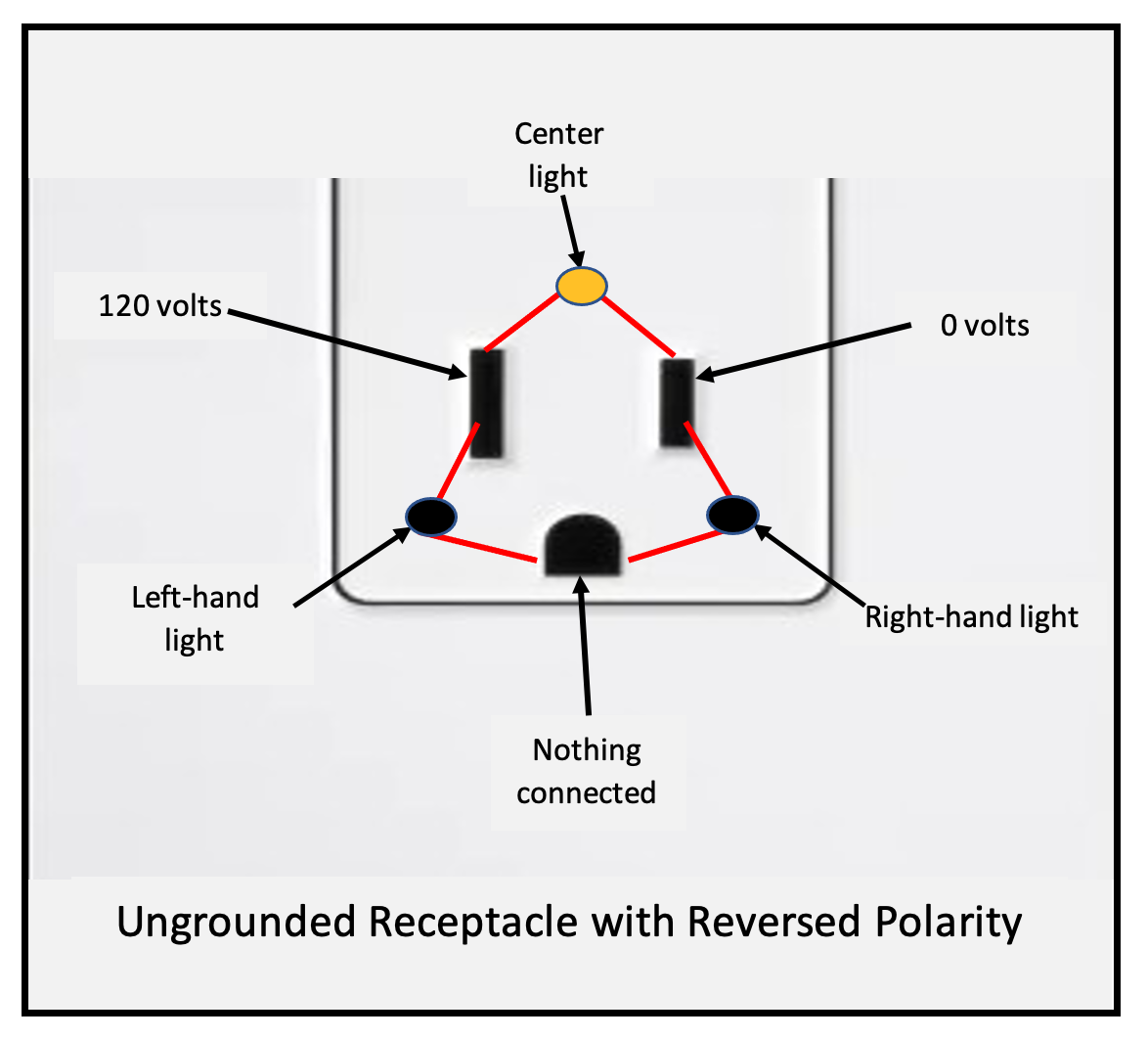

Indication on tester
It is because of this characteristic of three-light testers that you can get the same set of lights illuminating on two receptacles that are wired very differently.
An Extreme Example
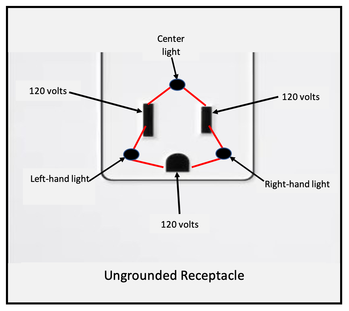
An extreme example is that you could theoretically connect a hot wire to all three slots of a receptacle. Before reading on, what do you think will happen? Will all the lights on the tester light up? Take a minute to think about it.
If you plug your tester into this receptacle, NO lights would illuminate because there would be no voltage difference between any of the three slots. (See diagram below.)
As you understand these testers and how they work, you will be able to better understand what they are telling you, and this will make these testers much more useful for you.
© 2021 Mike Morgan
This article was written by Mike Morgan, the owner of Morgan Inspection Services. Morgan Inspection Services has been providing home, septic and well inspection services throughout the central Texas area since 2002. He can be reached at 325-998-4663 or at mike@morganinspectionservices.com. No article, or portion thereof, may be reproduced or copied without prior written consent of Mike Morgan.

